PComp – Lab 1
Finally had the time to check this board out. Having not touched the thing since class a week ago, I stepped in all the bear traps waiting for the new user. It was hilarious, I had no troubles with the breadboard, meanwhile forgetting to install the driver was the first time burner. Then not uploading to the board was the second mistake. Once Aaron & Maria called out my goober, I was good to go, and clicked my LEDs on/off.
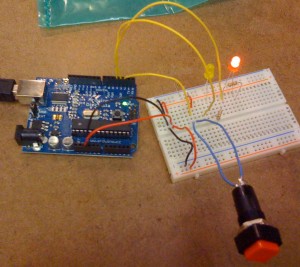
The breadboard itself is old hat for me. I must say, this is a bit easier than getting the PIC programmer running. I’ll go ahead and recount anyway. Connecting the 5V to the (+) and GRD to the (-), gave the board power and a place to ground. Popped in an LED (long leg +) across the two leads, and viola, Rudolph.
Getting familiar with electron flow and the pins on the Arduino board, I used the 5V DC from the Arduino to power an LED on a breadboard.
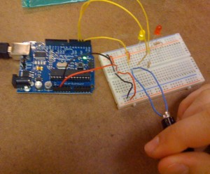
The next step was to connect a switch to the Arduino, that I would test its state (HIGH or LOW) with my code. If the switch was closed, it would send the 5V back to the Arduino and satisfy a test for HIGH. If the switch were open it would not return any voltage, and be set to LOW. In the code, I set up a conditional that if the switch was closed, light the yellow LED, otherwise, light the red LED.
Once I started using HIGH and LOW values in the Arduino program, the voltage came from the digital pin outs, in this case I used 2 for the switch, and 3 and 4 for LEDs, as per the class example. If the switch was pressed, I’d use the function digitalRead(#), # being the pin I’m listening to. Using a conditional statement, I used digitalWrite(#) to switch on LEDS with HIGH or off with LOW.
Working in the shop was a lot of fun, albeit super distracting. I think I helped troubleshoot four projects or so before even getting my basic Lab completed. Aaron & Maria were having a lot of fun behind me, working on a way to hook arrange Dominos as 3 or 4 sequence combination lock. The problem they were having was that they were sending separate pins to each domino, but they all had the common ground. I proposed they use the analog in on the Arduino. I searched on the Arduino site that the pin gives a digital value of the analog voltage between 0 and 1023, so I proposed that they should add a different amount of resistence to each domino, take readings and write if-statements correlating to the results.


Add your comment below, or trackback from your own site.
Subscribe to these comments.
Be nice. Keep it clean. Stay on topic. No spam.
You can use these tags: <a href="" title=""> <abbr title=""> <acronym title=""> <b> <blockquote cite=""> <cite> <code> <del datetime=""> <em> <i> <q cite=""> <s> <strike> <strong>